Mini City Rail

A personal project · in design

Mini City Rail

Lay out an N-scale Kato Unitrack mini city like a city-builder game, and get back the shopping list and the 3D-print files for everything around the track.

A macOS desktop planner, to be written in Rust with Bevy and egui. You paint ground and drag track on a 124 mm grid. It works out which Kato pieces to buy, then generates printable ground, raised levels, ramps, walls, bridges and piers that fit them.

Status: in design. There is no application code yet. Everything on this page is a drawing, a mockup or a prototype from the design work, and nothing has been printed yet.

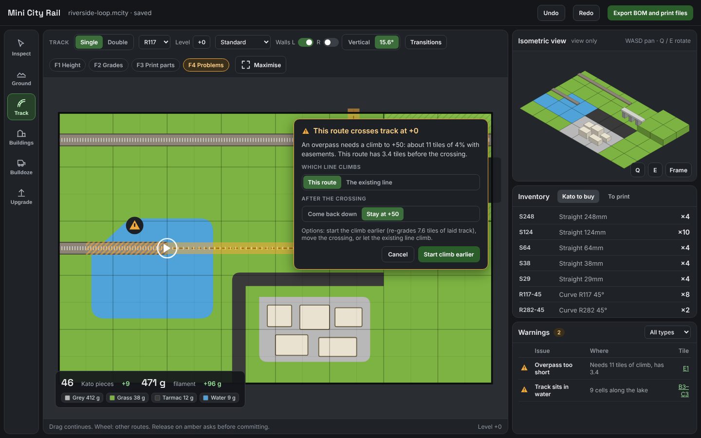
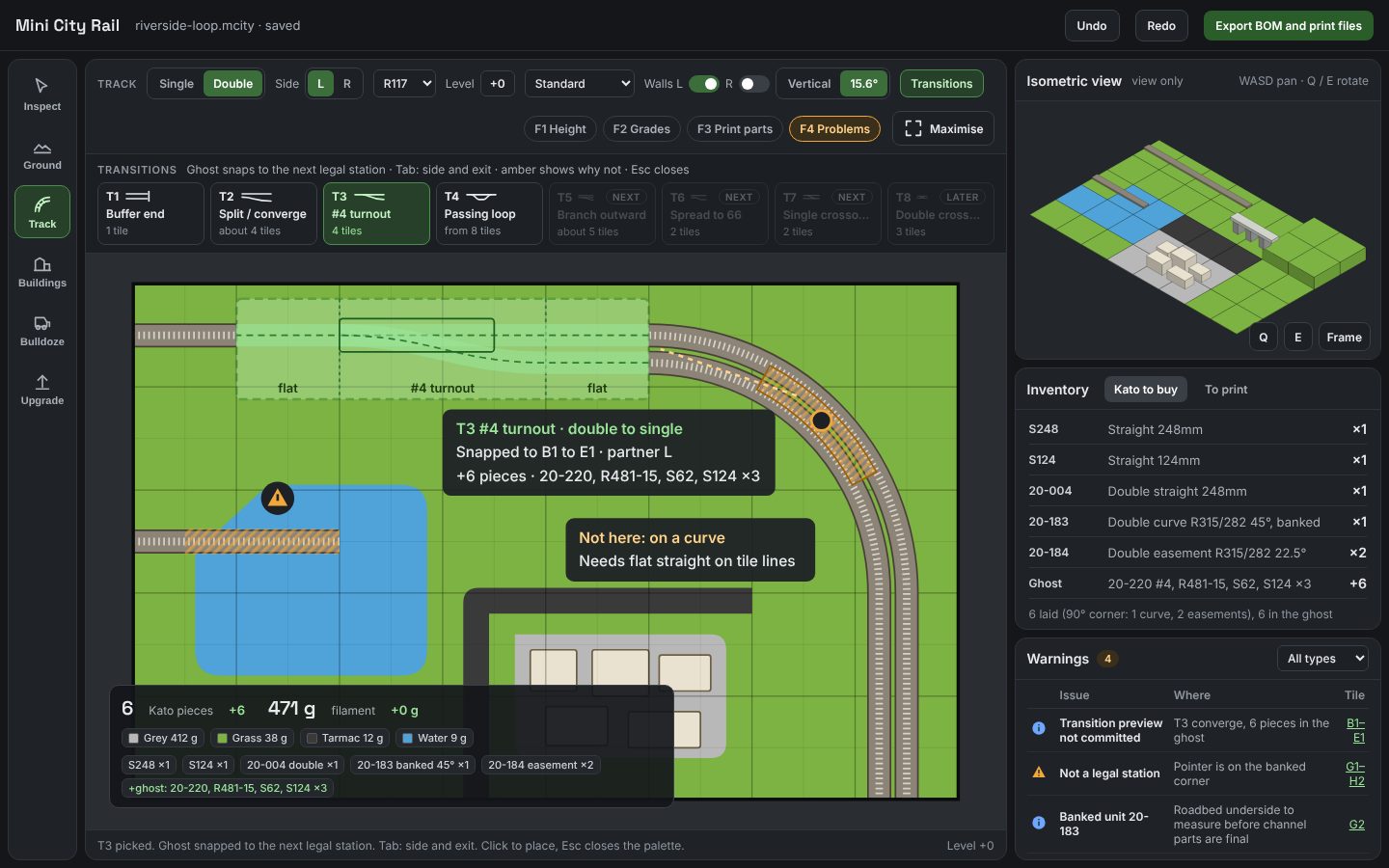
Mockup of the planner window: a plan view of a small layout with a lake and a double-track curve, a palette of track transitions above it, an isometric view, a parts inventory and a warnings table on the right. , open larger image
Mockup, not a screenshot. Placing a #4 turnout (Kato’s points) from the Transitions palette. The ghost snaps to the next spot where a turnout is allowed, explains in amber why it cannot go on the curve, and the counter shows the six Kato pieces it would add.
  • 124 mm tile, the length of one Kato S124 straight
  • 15.5 mm paint cells for grass, tarmac, grey and water
  • 50 mm steps of printed lattice for raised land
  • 280 × 280 mm default print bed; every part is checked against it
The idea

Track you can buy, a city you print

Kato Unitrack clips together in fixed lengths and radii, with the roadbed built in. That makes it ideal for a small layout on a table, but it leaves the hard part to you: ground that meets the track exactly, raised land, ramps, retaining walls and bridges that line up with real piece joints.

Mini City Rail is meant to close that gap. You plan on a grid that matches the track: one 124 mm tile is one S124 straight, and the pins that hold the printed parts sit on a 62 mm grid of holes in the baseboard. Because the planner knows exactly which Kato pieces you laid, every printed part can be generated to fit them, not picked from a catalogue.

It is built for one layout and one person: my own modular N-scale mini city. It will run on my Mac. No accounts, no cloud, no money.

How it plays

A city builder, not CAD

Pick a tool, then act. Every edit happens in the 2D plan; the isometric view beside it only shows the result, and follows along live. Esc always returns to Inspect.

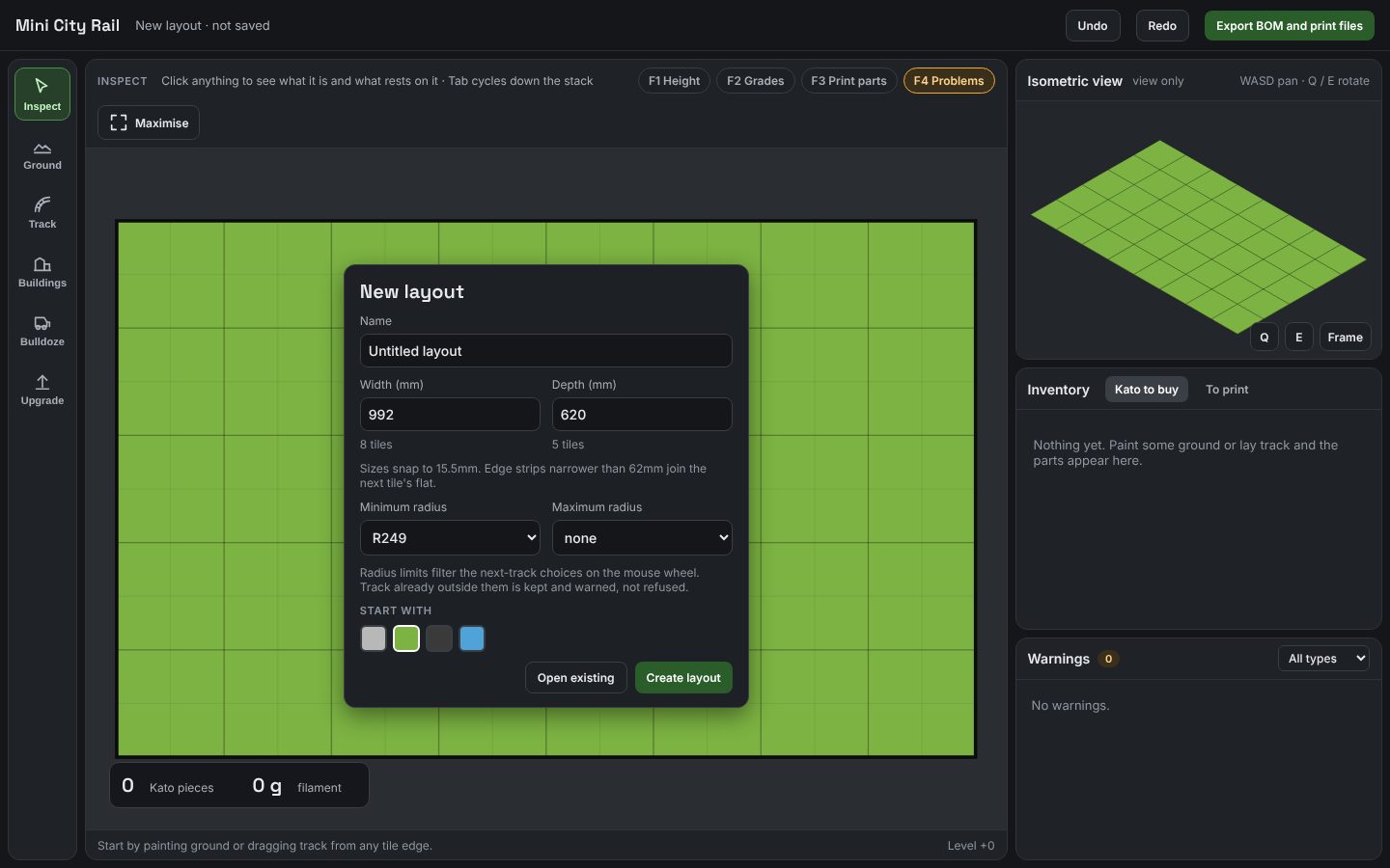
  1. Start a board. Give it a size (in multiples of 15.5 mm), a minimum radius (R249 by default) and a starting ground colour (grass by default).
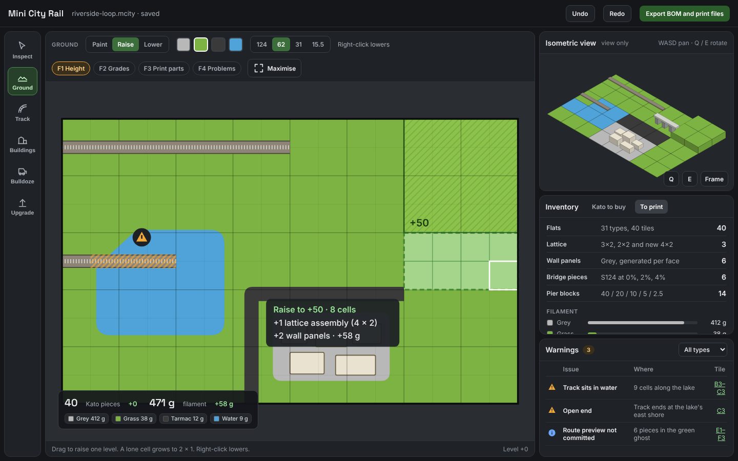
  2. Shape the ground. Raise and lower land one 50 mm level at a time, add two-tile scenery ramps between levels, and paint cover per 15.5 mm cell in grass, tarmac, grey or water. Water sits flush with the ground.
  3. Drag track. Drag from an open end and a solver picks the Kato pieces: straights, curves and the short fillers that land the next joint back on the grid, within 1 mm. The mouse wheel or Tab cycles through alternative routes, always in the same order.
  4. Read the ghost. The route under the cursor is green if it fits, amber if it fits with a catch, red if it cannot, with a one-line reason at the cursor: ‘Needs 11 tiles of climb, has 3.4’. Releasing the mouse commits exactly what the ghost showed, as one undo step.
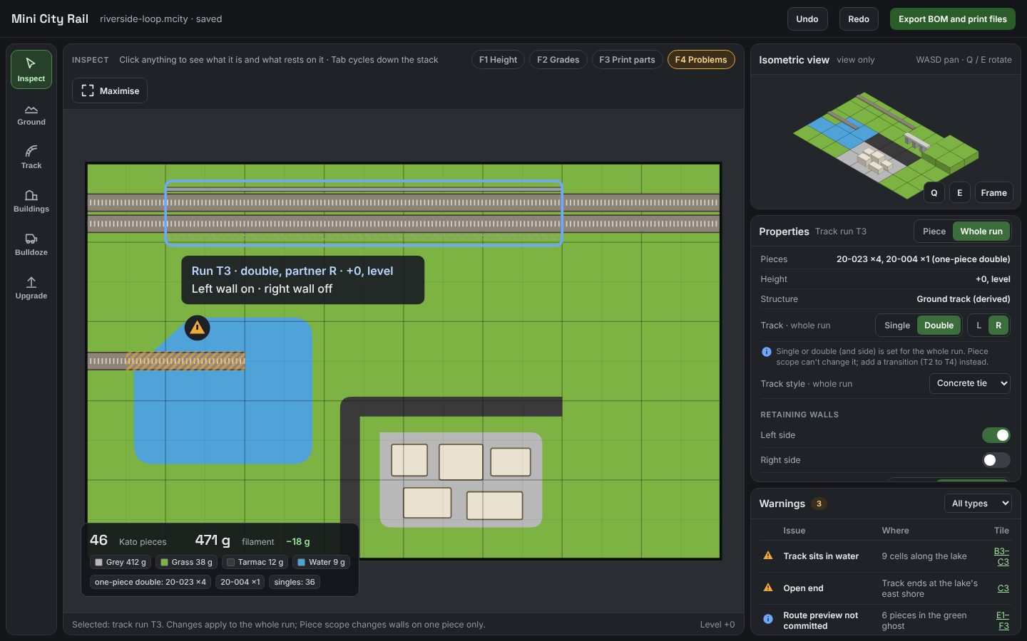
  5. Flip the overlays. F1 heights, F2 grades, F3 print parts, F4 problems. Problems show as icons on the plan as well as in a warnings table, and clicking a warning zooms both views to it.
  6. Watch the counter. An always-visible counter shows how many Kato pieces the layout uses and how many grams of filament each colour needs, and the ghost shows the change before you commit. There is no money anywhere in the game.
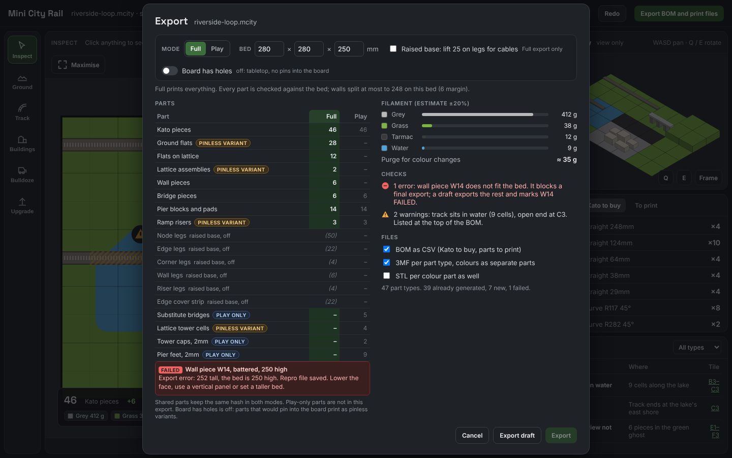
  7. Export. One button writes a parts list (Kato pieces to buy, parts to print) and the print files.
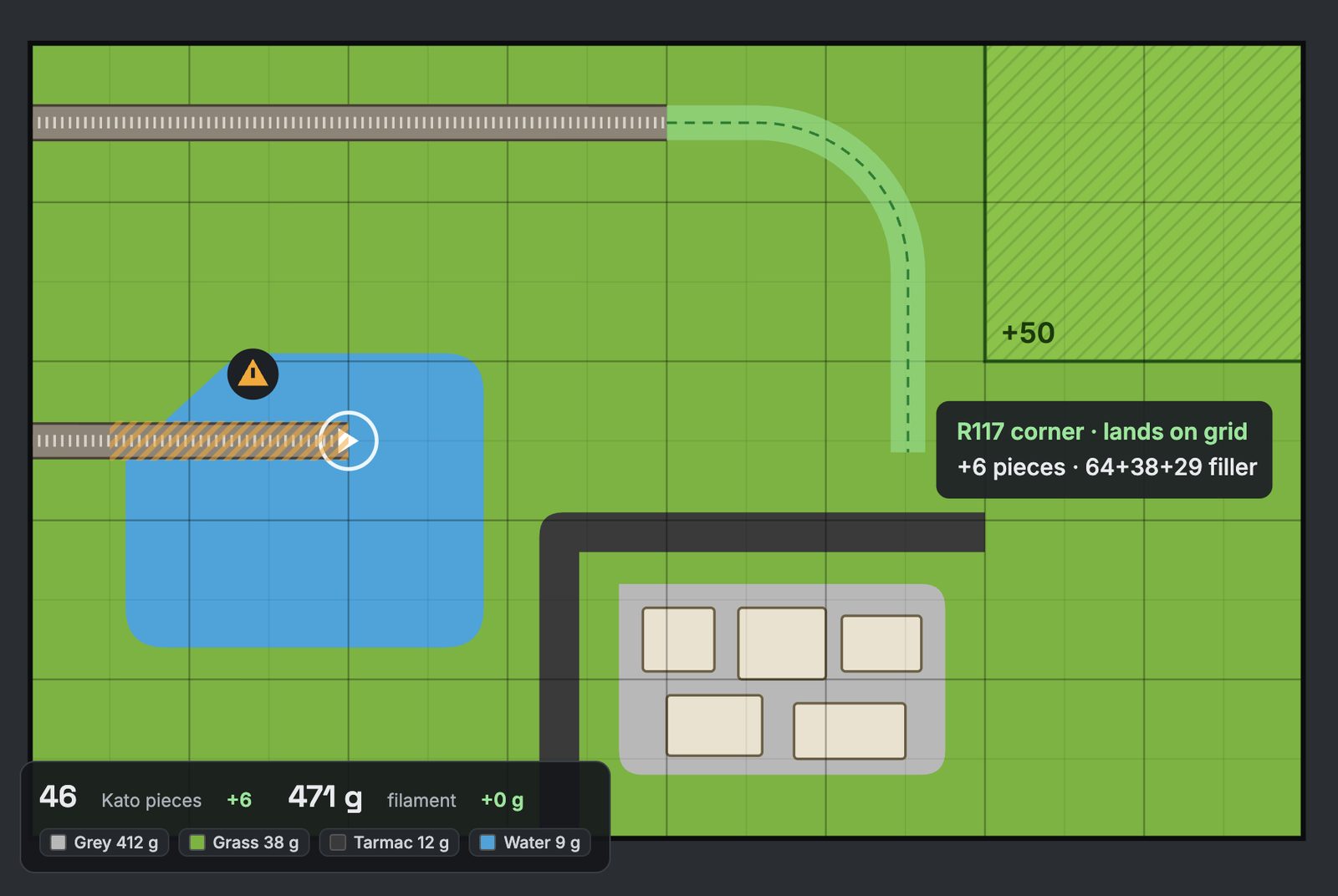
Mockup of the plan view: a green dashed ghost of a track corner curving down from a straight, a lake with a warning icon, a grey yard with placeholder buildings, and a counter showing 46 Kato pieces and 471 grams of filament. , open larger image
Mockup. Dragging a route: the green ghost is an R117 corner that lands on the grid, adding six pieces including a 64 + 38 + 29 mm filler. The counter shows 46 Kato pieces and 471 g of filament, split by colour. All numbers are illustrative.

Tools and keys

  • Inspect Ground Track Bulldoze
  • Esc back to Inspect
  • F1 to F4 overlays
  • Wheel or Tab next route
  • WASD pan and Q E rotate the iso view

The mockups also show Buildings and Upgrade on the tool rail; both come after the first version.

Principles

The rules it is built on

A planner that produces real parts has to be strict about a few things. These are the decisions everything else follows.

01

Store the intent, derive everything else

The layout file records only what you placed: ground levels and colours, track runs and their settings, transitions and ramps. Track channels, ground flats, lattice, bridges, piers, walls and the parts list are all recomputed from it after every edit and never saved. Nothing derived can drift out of step, and undo brings everything back exactly.

Diagram The pipeline: layout intent, then derived parts, then the parts list and print files Layout intent (ground levels and colours, track runs and transitions) is the only thing saved. After every edit the whole pipeline runs again and turns it into derived parts: channels, flats, lattice, bridge pieces, piers, walls and warnings, which are never saved. Export writes the parts list and the print files. Layout intent saved, and nothing else Ground levels and colours Track runs and their settings Transitions and ramps derive Derived parts recomputed, never saved Channels, flats and lattice Bridge pieces, piers, walls Warnings and the counter export Parts list, print files written when you export Kato pieces to buy Parts to print, with counts 3MF per part type, plus STL after every edit, the whole pipeline runs again
  1. Layout intent

    saved, and nothing else

    • Ground levels and colours
    • Track runs and their settings
    • Transitions and ramps
  2. Derived parts

    recomputed, never saved

    • Channels, flats and lattice
    • Bridge pieces, piers, walls
    • Warnings and the counter
  3. Parts list, print files

    written when you export

    • Kato pieces to buy
    • Parts to print, with counts
    • 3MF per part type, plus STL
The whole system in one line: thirteen derivation stages turn what you placed into parts after every edit, and export writes them out.
02

Ground first, track on top

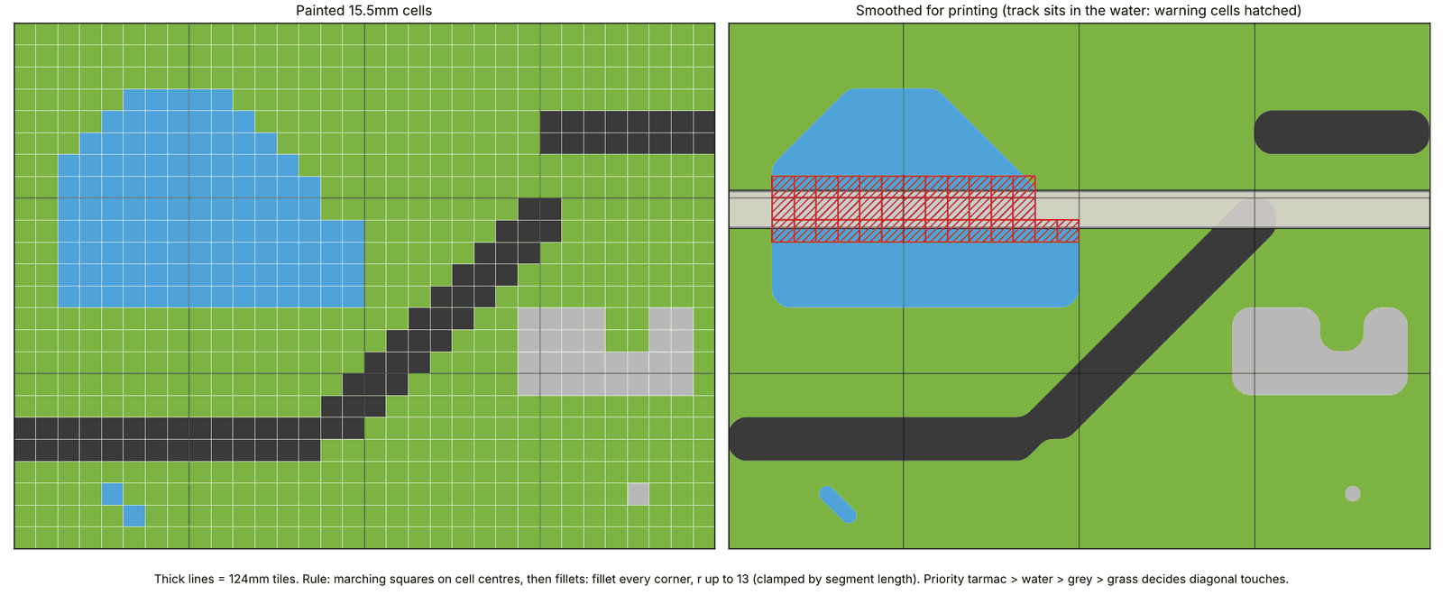
You shape and paint the land first. Things laid on top of it (track now, roads later) bury the shape of the ground but never its colour, so recolouring under anything is always allowed. Painted cells are smoothed by a fixed rule, staircases into clean 45 degree lines with rounded corners, so what prints looks drawn rather than pixelated.

Two panels: on the left, ground painted in small square cells of grass, water, tarmac and grey; on the right, the same ground smoothed into rounded shapes and diagonal roads, with a track crossing the water and the cells under it hatched in red. , open larger image
Prototype. Painted 15.5 mm cells (left) and the smoothed shapes that get printed (right), with corners rounded up to 13 mm. Where colours meet, tarmac beats water, water beats grey and grey beats grass. Track may cross water, and every water cell under it carries a warning.
03

The top-layer rule

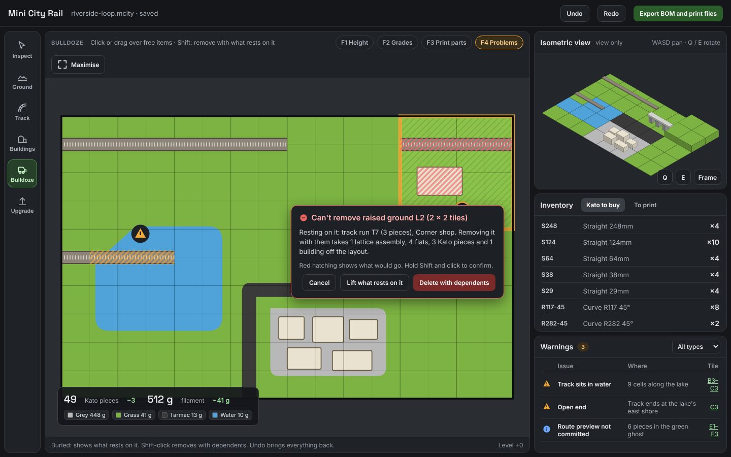
Anything with nothing resting on it is free: move it, reshape it, re-height it or delete it. Anything with something on it is buried and locked, and the refusal names exactly what rests on it. There are honest ways round: adding on top is always allowed, colour can always change, a buried thing can be deleted together with everything on it after a preview, or you can lift what rests on it, edit underneath and put it back. Nothing is ever deleted silently.

Mockup of the Bulldoze tool refusing to remove a raised 2 by 2 tile area, with a card listing what rests on it and buttons for Cancel, Lift what rests on it and Delete with dependents. , open larger image
Mockup. Bulldoze refuses to remove raised ground with track and a building on it (buildings themselves come much later), says what would go with it (shown hatched in red), and offers to lift those items off or delete them together. Undo brings everything back.
04

Same layout, same parts

Every free choice the generators could make is closed by a numbered rule, 48 of them plus the double-track rules, so the same layout always gives the same parts. Each printed part is identified by a hash of its parameters, in whole micrometres and in the part’s own frame. Identical parts share one file and a count, files are named by kind and hash, and part numbers stay put from one export to the next.

part  count  file
F12    × 8   parts/flat-3fa9c2d1e0b4a7c6.3mf
F31    × 28  parts/flat-82c0e5a91d4b7f03.3mf
K3     × 6   parts/pier-block-5e19b0c4a7d2f816.3mf
B9     × 5   parts/bridge-c47a1e9036b5d2f8.3mf
L2     × 3   parts/lattice-0d6b3f28e1a95c74.3mf
Illustrative export. Each part type is one file, named by its kind and the first 16 hex digits of its hash, printed as many times as the count says. The part number (F12, K3) is what is debossed on the part and listed in the parts list.
05

One track on the grid

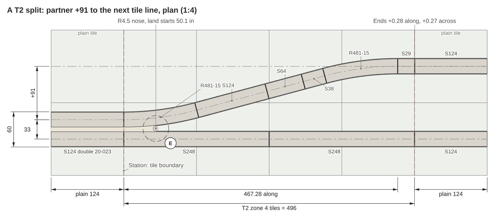
No combination of Kato pieces moves a track 16.5 mm sideways, so a double track centred on the grid could never meet a single without a long jog. Instead one track of a double sits exactly where a single would, and its partner runs 33 mm to one side. Doubles then join singles cleanly, through splits, #4 turnouts and passing loops. Kato’s one-piece double track and banked curves are used wherever they fit, and the easements (short transition curves) those curves need are added to the parts list automatically.

Plan drawing of a double track splitting over four tiles: one track runs straight on while the other curves 91 millimetres across to the next tile line, with every Kato piece labelled. , open larger image
Drawing (proposed), sheet 9. A split over four tiles: the partner track moves 91 mm to the next tile line using two R481 15 degree curves and straights, and lands 0.28 mm along and 0.27 mm across from exact, inside the 1 mm tolerance.
06

Play now, scenery later

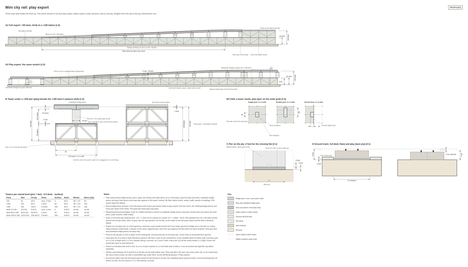
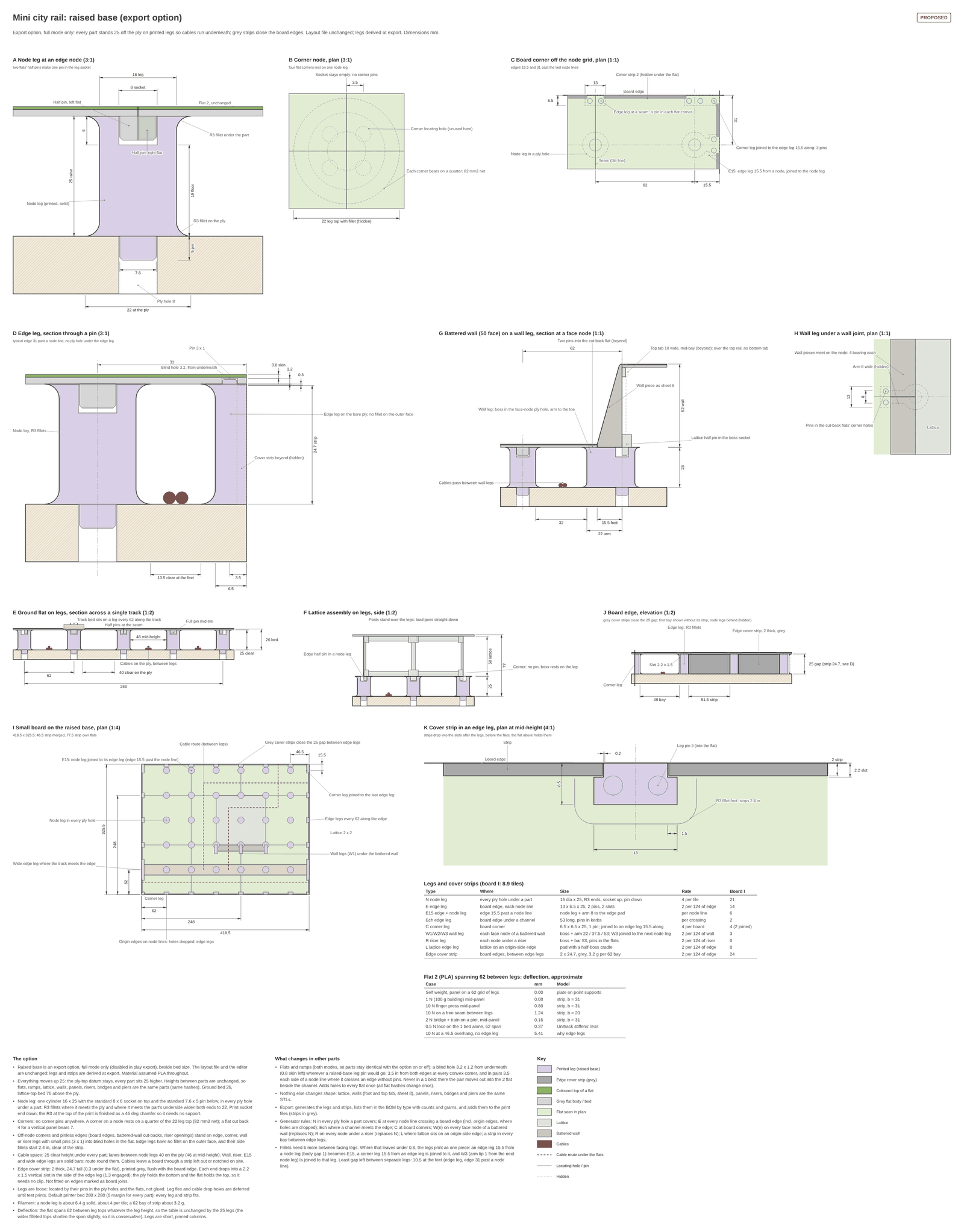
A play export prints only what holds the track up: bridge pieces, piers and risers, with bridges standing in for raised land, so trains can run before any scenery exists. A part that appears in both exports is the same part with the same hash. For the full export, an optional raised base lifts everything 25 mm on printed legs so cables run underneath. In either export, turning off ‘Board has holes’ drops the board pins for a plain tabletop. The layout itself never changes; these are export settings.

Elevation drawing: on the left, a substitute bridge piece on a pier standing on a small two by two cell lattice tower (play export); on the right, the two levels of lattice and the flat it replaces (full export), with the track bed at 101 millimetres in both. , open the whole sheet
Detail from sheet 10 (proposed). In a play export a pier taller than 42.5 mm stands on a small tower of lattice cells instead of the full raised land, and the track bed is at the same height in both. Tap or click for the whole sheet.
Section drawing of a ground flat on the raised base: printed legs every 62 millimetres hold it 25 millimetres above the ply, with cables running between them. , open the whole sheet
Detail from sheet 11 (proposed). The raised base: printed legs every 62 mm hold a flat 25 mm up, leaving room for cables on the ply. Tap or click for the whole sheet.
07

Printable at home

Every part is checked against the printer bed: 280 × 280 mm by default with a 6 mm margin, changeable per export. A part that is too big is split at a declared place (flats on cell lines, bridges at Kato joints, walls on 62 mm nodes), or the export says plainly which part will not fit and why. Ground flats print one per tile with a grey body and the colour in the top 0.6 mm, ready for a multi-colour printer. Filament is estimated per colour, to within about 20 percent.

There is no printer yet, so none of this has been test-printed. Fits, clearances and wall thicknesses are proposals until it has.

What it makes

A shopping list and a folder of parts

Two outputs. A parts list says what to buy and what to print. The print files are generated for this layout, so every bridge piece, flat and wall is exactly the one it needs.

The parts list

A CSV in two halves: Kato to buy, counted the way Kato sells it (packs of two, left and right easements), and parts to print, with part numbers, counts and filament grams per colour. Warnings head the list.

The print files

One 3MF per part type, with the grey body and each colour as separate parts so a multi-colour slicer (the program that prepares a print) assigns them by itself, and STL per colour as a fallback. A manifest lists every file. If one part fails to generate, it is marked FAILED with a file to reproduce it, and the rest still export.

Part families

Every family has a dimensioned drawing. All of them are marked PROPOSED: they fix the numbers the code will use, but nothing has been printed yet. Each card shows one detail; tap or click it for the whole sheet.

Ground flats with the channel cut in

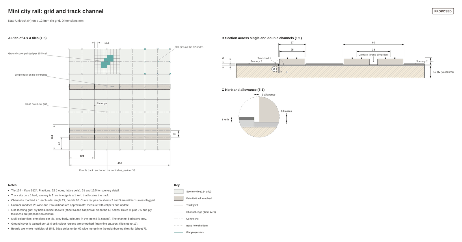
One flat per 124 mm tile. The track sits in a channel 1 mm wider than the roadbed on each side (27 mm for a single, 60 mm for a double) on a 1 mm bed, so the kerb locates the track. Pins underneath drop into a 62 mm grid of holes in the ply.

Section across a single track channel: the 25 millimetre Unitrack roadbed sits in a 27 millimetre channel, 1 millimetre into 2 millimetre scenery on a ply base. , open the whole sheet
Detail from sheet 1 (proposed). A section across a single channel, with the 1 mm kerb either side of the roadbed. Tap or click for the whole sheet.

Corners that land on the grid

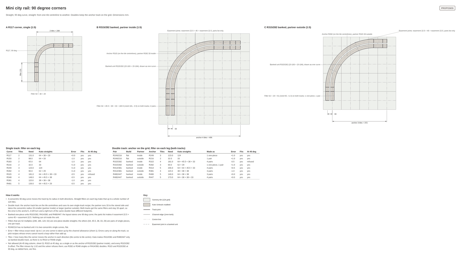
A 90 degree curve moves the track by its radius, which is never a whole number of tiles. Each corner is a recipe of Kato pieces plus fillers that brings the track back onto the grid within 1 mm. The tables are worked out, not guessed: an R117 corner with 64 + 62 + 38 + 29 mm of filler lands exactly on the grid, and any recipe whose leftover error exceeds 1 mm is never offered.

Plan of a banked double-track 90 degree corner, R315 with its R282 partner inside, on a grid of 124 millimetre tiles, with the filler straights on each leg labelled. , open the whole sheet
Detail from sheet 2 (proposed). A banked R315/282 double corner across four tiles, with its fillers and easements. Tap or click for the whole sheet.

Raised land in 50 mm lattice

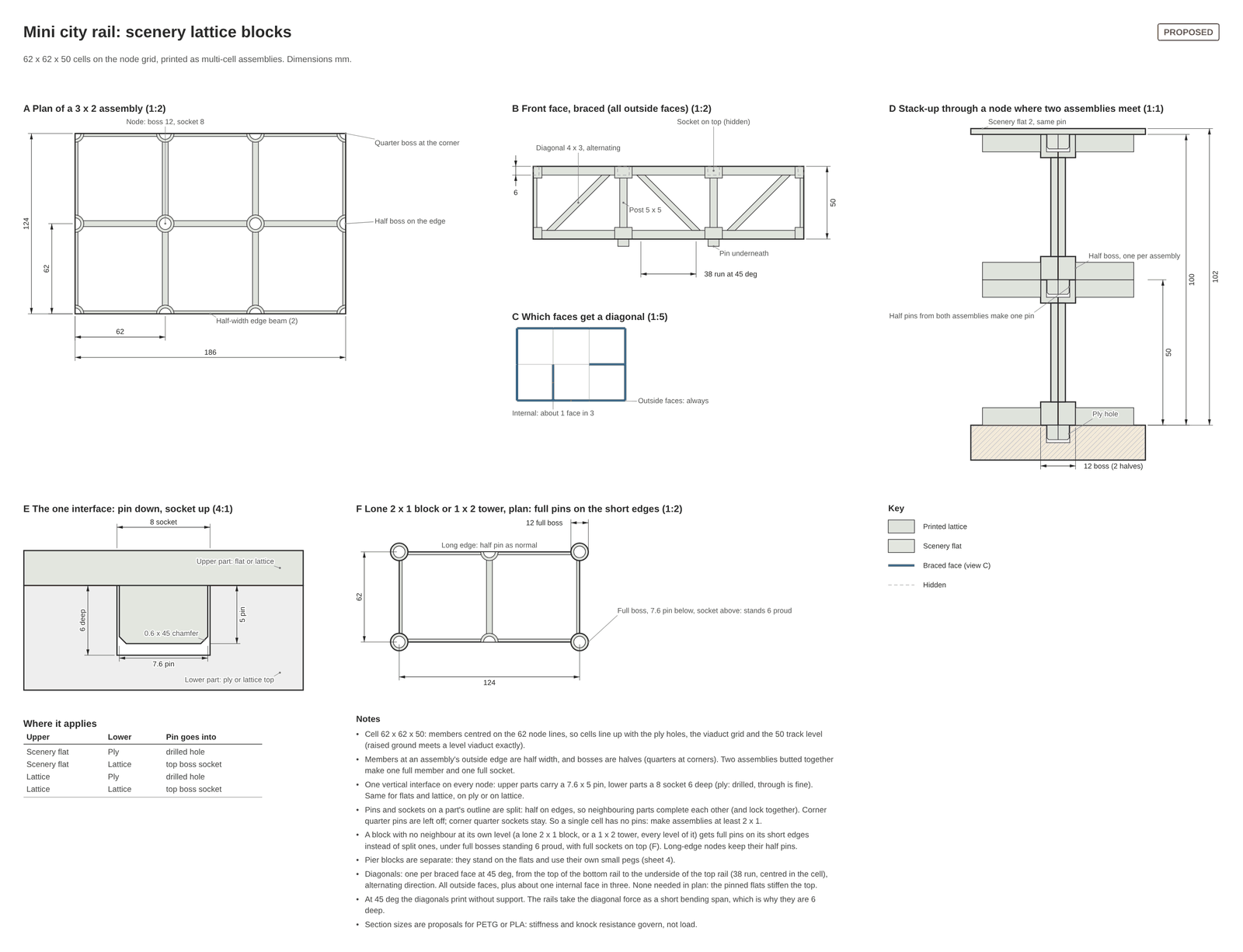
Raised ground is printed lattice: 62 × 62 × 50 mm cells joined into assemblies that fit the bed, braced on every outside face. One pin-and-socket joint is used everywhere, so flats sit on the ply or on lattice in exactly the same way, and lattice stacks on lattice.

Front face of a lattice block: two 62 millimetre cells, 50 millimetres high, with alternating diagonal braces and pins underneath. , open the whole sheet
Detail from sheet 6 (proposed). The braced face of a two-cell lattice block. Tap or click for the whole sheet, with the pin-down, socket-up joint every part uses.

Climbs and piers

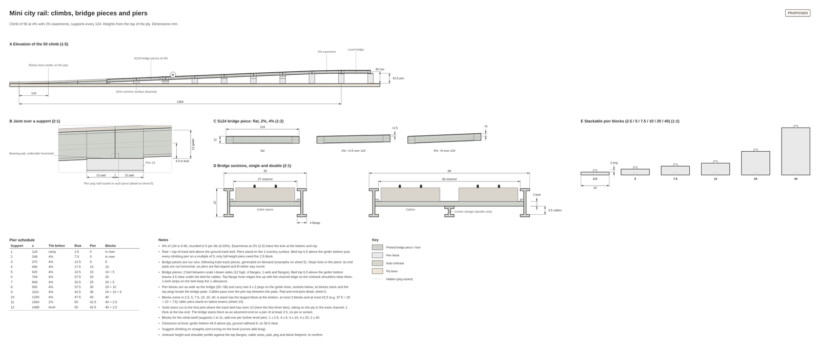
Track climbs at 5 mm per tile (4.03 percent) with 2 percent easements at each end, so reaching +50 takes about 11 tiles. Solid risers carry the first few tiles; after that the track is on bridge pieces over piers stacked from 2.5, 5, 7.5, 10, 20 and 40 mm blocks. Crossings become overpasses with 36.5 mm of clearance.

Six stackable pier blocks, 2.5, 5, 7.5, 10, 20 and 40 millimetres high and 24 millimetres wide, each with a 2 millimetre peg on top. , open the whole sheet
Detail from sheet 4 (proposed). The six stackable pier blocks. Tap or click for the whole sheet, with the climb to +50 tile by tile.

Bridge pieces

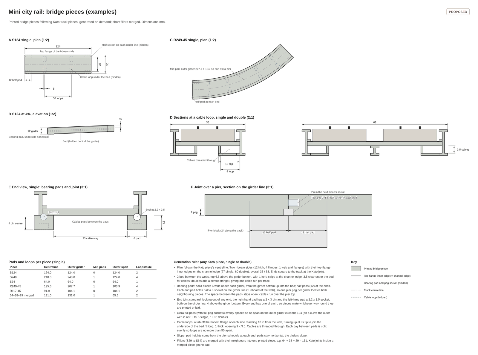
Every Kato piece in the air gets its own printed bridge piece that follows its centreline: I-beam sides, bearing pads at the joints, and cable loops underneath. Short fillers merge into their neighbours, and pieces join with a pin on one side and a socket on the other, so they fit whichever way round they are laid.

Plan of a curved printed bridge piece following a Kato R249 45 degree curve, with the hidden bearing pads dashed and a note that the outer girder needs one extra pier. , open the whole sheet
Detail from sheet 5 (proposed). A curved bridge piece under an R249 45 degree curve. Tap or click for the whole sheet.

Retaining walls

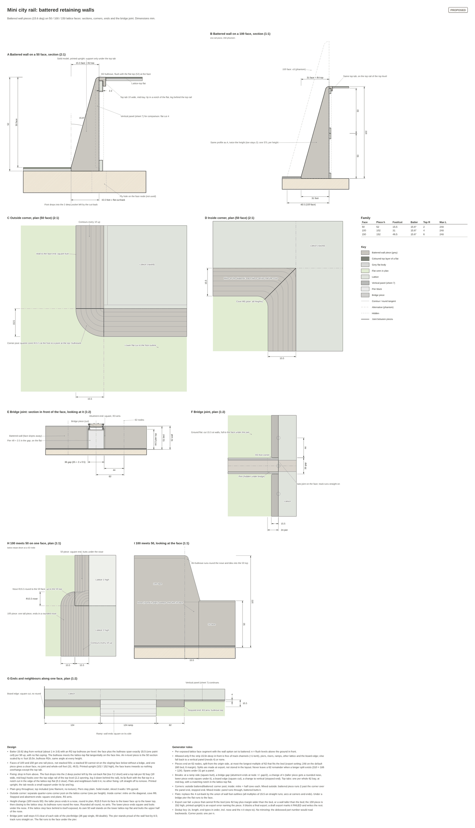
Exposed lattice faces get walls, vertical or battered at about 15.6 degrees, set per side on any track or face. A wall drops in from above and is held by its foot and a tab over the lattice rail, with the flats around it locking it in. No glue.

Section drawing of a battered retaining wall 50 millimetres high, leaning at 15.6 degrees, with its foot in the lower flat and a top tab hooked into the lattice-top flat. , open the whole sheet
Detail from sheet 8 (proposed). A battered wall on a 50 mm face: the slope plus a 2 mm rounded top fill exactly one 15.5 mm cell per level. Tap or click for the whole sheet.
Mockups

What it should look like

These are static mockups, made to settle the layout and the wording before any code is written. They are not screenshots, and the numbers in them are illustrative. The planned app uses the same dark theme and green accent as this page.

Implementation design

Under the hood

The implementation design is written down to the level of types and tests, and is still under review. The short version:

Rust, native on macOS (Apple Silicon), in a Cargo workspace of thirteen crates. The boundaries between them are rules an automated check enforces: Bevy, egui and the geometry kernel are each confined to one or two crates; the track solver cannot see flats or solids; the geometry crate never sees a layout; and no domain crate touches files, clocks, randomness or hash maps. Every length is a whole number of micrometres, and track headings come from an exact table rather than sine and cosine, so the same layout always gives the same parts with the same identifying hashes.

The first thing to be built is not the app but a command-line tool, mcr: load a layout file, write the parts list and the print files. It proves the generators before any UI exists.

Diagram
  1. layer8
    mcr-appBevy host, iso view, files, platform code
  2. layer7
    mcr-uiegui shell, plan view, panels
    mcr-clithe mcr command
  3. layer6
    mcr-editorcommands, undo, tools, ghosts
    mcr-export3MF, STL, CSV, manifest
  4. layer5
    mcr-scenethe plan scene, shared by the editor and export
  5. layer4
    mcr-derivethe derivation pipeline, warnings, parts list
  6. layer3
    mcr-trackKato recipes, solver, grades
  7. layer2
    mcr-modellayout intent, file format
    mcr-geometrysolids from part specs
  8. layer1
    mcr-specconstants, Kato catalogue
    mcr-partspart specs and hashes
  9. layer0
    mcr-baseunits, grids, exact trig, polygons, hashing
Each crate depends only on crates below it. mcr stands for Mini City Rail.
  • One pipeline. Thirteen stages in a fixed order turn intent into parts: normalise, ground, track, classify, channels, elevated, walls, cover, flats, legs, support, parts, issues. Every stage runs in full after every edit; the target is a fresh result within one frame (16 ms) on an 8 by 5 tile board. The one slow step, shaping a flat, is cached by the part’s hash, so the cache can never go stale. The UI thread never derives anything; one worker does.
  • Tests that pin intent. Tests use public interfaces only and are named after the requirement they protect, for example: r27_lone_2x1_gets_short_edge_full_proud_pins f16_undo_restores_layout_and_derived_exactly Where a rule is general they test a property: no joint ever exceeds the tolerance, no colour region is narrower than 3 mm, the same part built two ways has the same hash.
  • Goldens only where the output is the point. Goldens (saved reference outputs) cover the parts list for fixture layouts, the file schema and the table of part hashes. No snapshots of pixels or mesh bytes: solids are tested by validity, volume and their dimensions against the drawings.

Rust · Bevy and bevy_egui · manifold for solids · i_overlay for polygons · blake3 for part hashes · 3MF and STL out

Roadmap

Where it is going

  1. Done

    The design

    A specification of user stories and 48 generation rules; eleven dimensioned drawing sheets (plus one extra); UI mockups; a smoothing prototype; an implementation design for the Rust workspace; the Phase 2 train stories; and research into free train models.

  2. Next

    The command line

    The workspace, the constants and the Kato catalogue, the layout file, the Kato corner recipes and single-track layout, flats with channels and smoothed colour, the parts list, and 3MF and STL from the mcr command. Done when a ground-level loop builds into coloured 3MF files that open correctly in a slicer.

  3. First playable

    The smallest loop you can plan and print: one level, single track with 90 degree corners, painting, the iso view and print files. In the app you can paint, raise, drag track, bulldoze, undo, save and reopen, with the counter, inventory and warnings following every edit.

  4. MVP

    Everything described above the roadmap: climbs and overpasses, bridges and piers, 45 degree diagonals, double track with buffers, splits, #4 turnouts and passing loops, retaining walls, lift and put back, the play export, the raised base and boards without holes.

  5. After the MVP

    Phase 2: trains

    Designed now, built after the MVP, and changing none of its decisions. A train is a toy you put on the track, not a part you buy or print.

    • Real models at true size. Japanese narrow-gauge stock at 1:150; Shinkansen, European and US stock at 1:160, as Kato makes them. Each car sits on its two bogie pivots on the track centreline, so it swings out on curves as the real model does.
    • Trains that run themselves. Up to eight at once in the iso view, each with a speed control like a Kato power pack knob. They never derail or collide: they stop politely and say why.
    • A driver’s-eye cab view. Select a train and the iso view becomes the view from the front of the train, 3 m (prototype) above the rails. W accelerates, S brakes, and there is no reverse. A speedometer on the side shows the real speed in mm/s and the scale speed in km/h.
    • Will my trains run on this? Checks for curves too tight for a train, trains touching as they pass on a double-track curve, stock too tall for a bridge, and passing loops too short for the train. They advise; they never block.
    km/h = mm/s × scale / 1000 × 3.6

    Real millimetres, real seconds. A 1:160 Shinkansen-style train at 556 mm/s reads 320 km/h, and really crosses a 992 mm board in under two seconds. A 1:150 train at 222 mm/s reads 120 km/h.

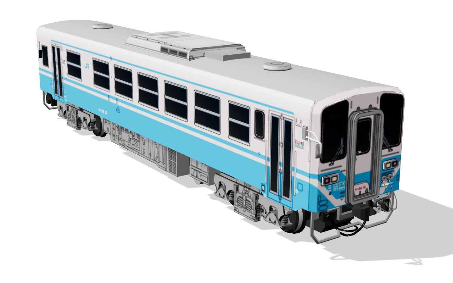
    Three-quarter render of a white and light blue Japanese single-car diesel railcar, the KiHa 32, seen from above one end. , open larger image
    Model research render. The JNR KiHa 32 diesel railcar by own.guest (CC BY 4.0), the planned default train, rescaled to 1:150, where it is 108.7 mm long. Full credit below.
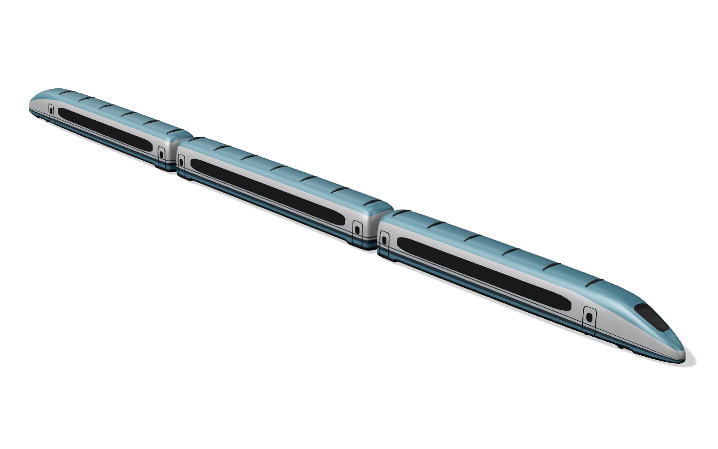
    Three-quarter render of a three-car low-poly Shinkansen-style train in silver and teal, with a long pointed nose at the near end. , open larger image
    Model research render. The three-car Shinkansen-style set from Quaternius’s Modular Train Pack (CC0), offered in the first train release to show multi-car swing. At 1:160 the three-car set is 491.5 mm long.

Later, briefly

After that: roads and road ramps, printed station platforms, an Upgrade tool, stickers, trees and props, several boards joined together. Buildings come much later.

Waiting on

A 3D printer, and a few measurements of real Kato track: the #4 turnout’s make-up and outline, the width and banked underside of the one-piece double track, and the buffer part numbers. Until then those numbers are kept as named, flagged values.

Licences

Credits

  • Kato and Unitrack are trademarks of Kato. This is an independent personal project, not affiliated with or endorsed by Kato.
  • KiHa 32 render: based on ‘国鉄キハ32形気動車 KIHA 32 Diesel’ by own.guest, licensed under CC BY 4.0. Modified: rescaled and rendered as a preview.
  • Shinkansen-style train render: from ‘Modular Train Pack’ by Quaternius, CC0 1.0 (no attribution required; credited with thanks).
  • Fonts: Inter and Space Grotesk, under the SIL Open Font License (Inter licence, Space Grotesk licence), self-hosted on this site.
  • Drawings, mockups and the smoothing prototype: from the project’s own design work.